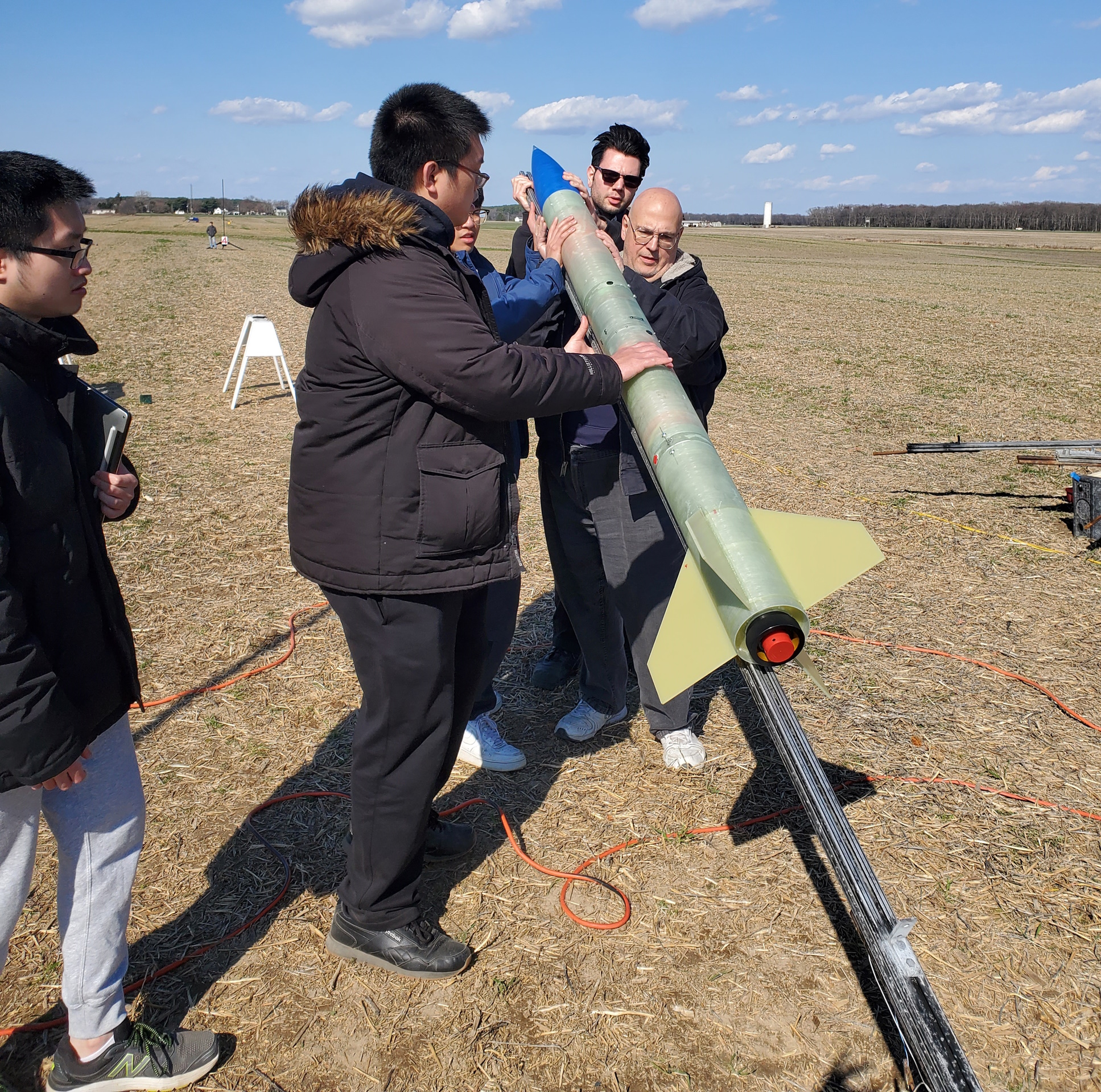
As the Payload Team Leader for the 2023 NASA University Student Launch Initiative (USLI) Stony Brook Team, I led a student-driven project to develop a sophisticated rocket launched Radio Frequency Command (RAFCO) and camera payload system in accordance with this year’s challenge requirements. Our payload team’s mission was to design and integrate an automated camera system capable of swiveling 360º and autonomously executing a series of RF commands over APRS on VHF frequencies.
Intro to USLI
The NASA Student Launch Challenge, or University Student Launch Initiative (USLI), is an annual prestigious competition that invites teams of undergraduate college students from across the United States to design, build, and launch high-powered rockets carrying innovative payloads aligned to a yearly set of challenges. Through hands-on experience across all aspects of a development cycle, the initiative aims to inspire the next generation of aerospace professionals and promote interest in Science, Technology, Engineering, and Mathematics (STEM) fields.
The 2023 challenge focused on the development of a Radio Frequency Command (RAFCO) camera payload, requiring our team to design a deployment mechanism for the payload, a SDR receiver with AFSK1200 decoder for RAFCO, and a 360 degree camera system capable of operating autonomously via a series of RF commands. Upon landing, the payload system had to receive and process a sequence of tasks transmitted via radio frequency using Automatic Packet Reporting System (APRS) protocol to control the camera. The challenge aimed to test the teams’ abilities to integrate radio frequency communication systems, payload design, and autonomous control while adhering to specific performance criteria, such as response time and operating within designated frequency ranges. This unique challenge fostered critical skills in engineering, communication systems, and teamwork, preparing team members for real-world aerospace industry applications.
My role as Payload Team Leader
My role as the Payload Team Leader included being the primary manager of the payload team needing to enact and enforce deadlines and requirements to ensure the team was working steadily towards each milestone along the provided NASA timeline, as well as overseeing the direction of the design as we worked towards an end design capable of satisfying all the requirements as listed in the USLI Handbook. To accomplish this I would assign and relay tasks to each of the 4 other team members while also accomplishing a large amount of the design and fabrication work myself. To keep the project on schedule throughout the 8 months of work I had to familiarize and play towards each members strengths across several areas such as mechanical design, electrical design, and programming the systems to work harmoniously. Over the first month or so we had brainstormed the design of the payload, and then as we finalized our requirements and critical parts of the design I was responsible for distributing the tasks and managing the work of the team towards the final design.
Challenges of Working Within a Small Team
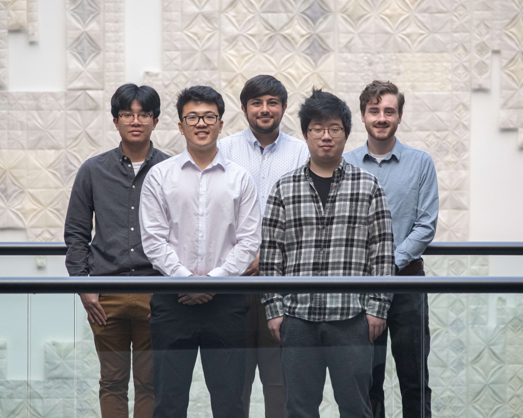
Due to the large scale of the project in comparison to the small team size (and even smaller compared with other contestant universities), coordination between team members was necessary to keep everyone aligned towards a similar goal, and keeping morale high and avoiding team burnout was critical. However in a small team of 5 total members, each member had to push past their comfort zone to challenge them and involve themselves in new areas not yet explored or covered in our academic work. This was especially the case in the electronics design of the payload, as we had all taken a basic practical electronics course, we were not familiar with the working of radio and complicated systems such as the one designed. This required a large amount of self-learning, especially in PCB design, where I had tasked each member with constructing small functional blocks for the electronics, before being collated together for a single PCB. Additionally, the team had to decided to learn to use SOLIDWORKS and SOLIDWORKS Simulation for the CAD of the payload, as well as running stress analyses on the designed parts before committing to a final design.
Payload Design and Development
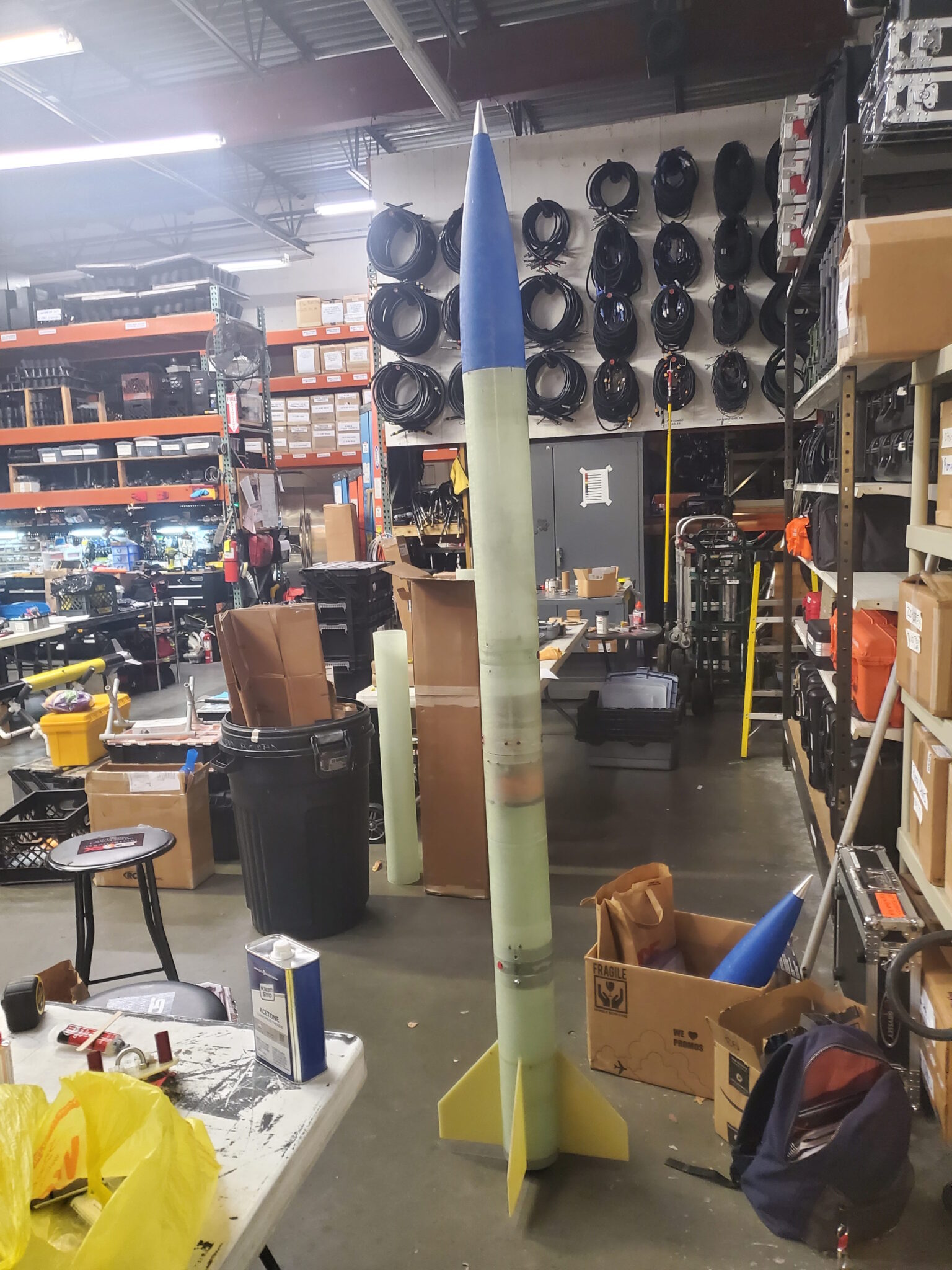
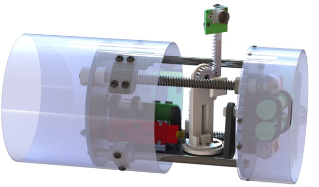
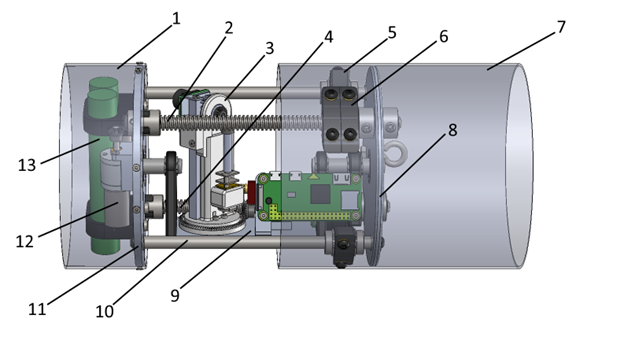
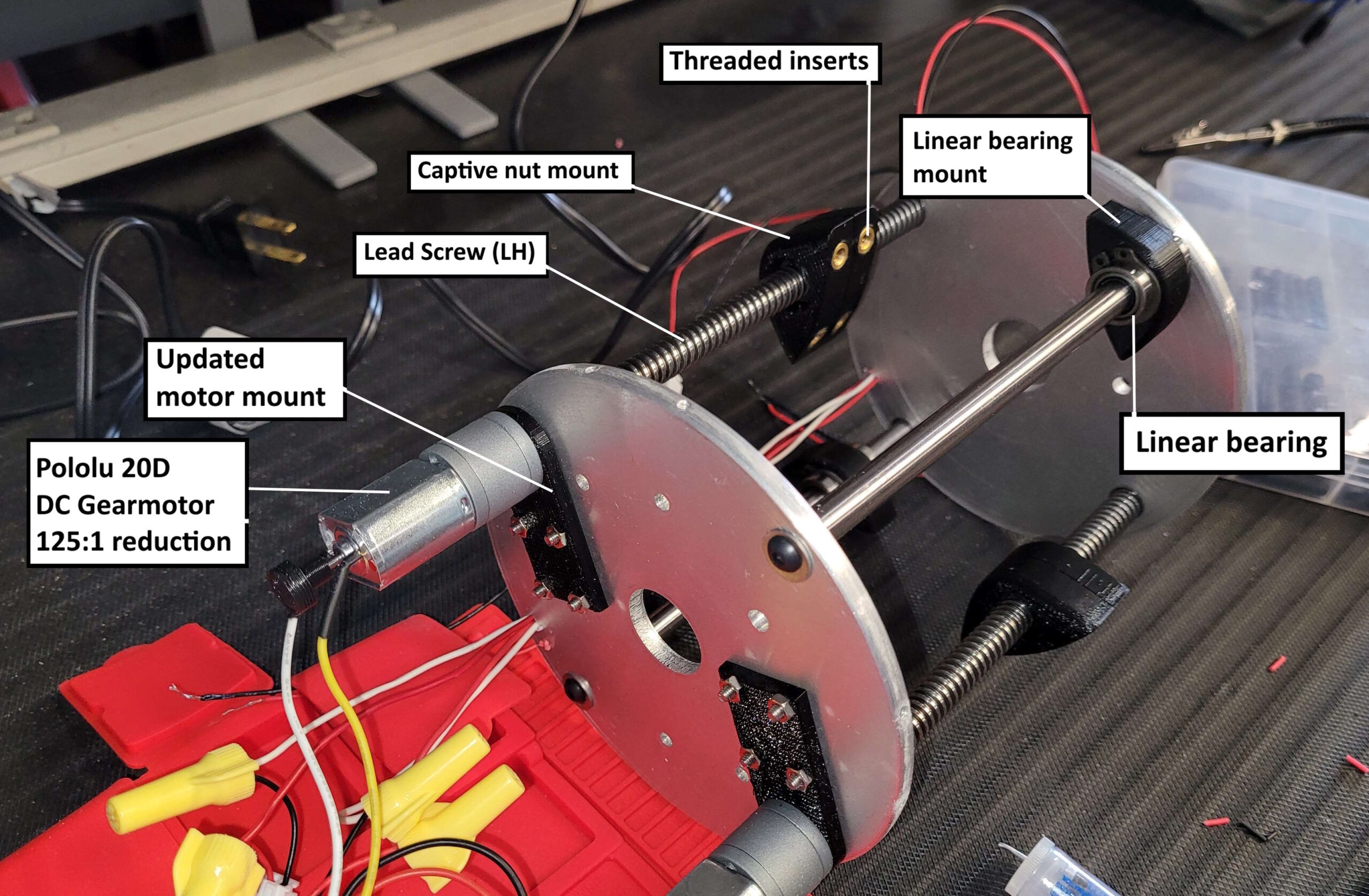
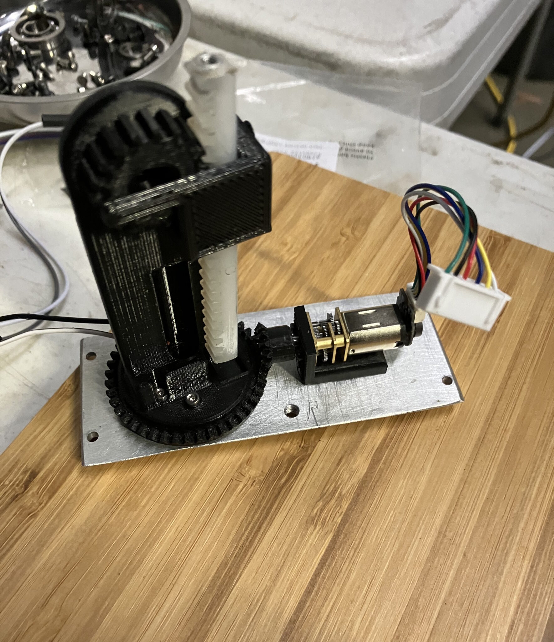
The basis of the payload consisted of a chassis made of laser-cut aluminum bulkheads and machined steel rods to be affixed within the fiberglass chassis of the rocket. Alongside the aluminum frame, the retention mechanism was built around the chassis with 2 lead screws each driven by a DC gearmotor to actuate the casing back and forth. The steel rods housed linear ball bearings to guide the motion of the casing as it translates along the lead screws. The electronics and camera system contained in the payload were mounted to a passively gyroscoping table mounted between a flanged ball bearing in each bulkhead. By designing the center of mass of the gyroscoping table assembly to be below the center line of the payload, gravity would naturally align the camera to the ground plane. For raising the camera to a vantage point above the launch vehicle a rack and pinion system was developed to lift the camera out of the casing. Processing onboard the payload was handled by a Raspberry Pi Zero 2W coupled to the custom PCB designed for this challenge, and radio messages were received using a RTL-SDR USB receiver. Additional components included a gyroscope for detecting launch and landing, as well as a gearmotor with a magnetic encoder to rotate the rack and pinion to specified angles achieving the ability to rotate in 360 degrees. The construction of the payload was limited to 9 inches and 3.0 pounds, with a total weight of 2.72 pounds after construction.
Key Mechanisms and Components of the Payload
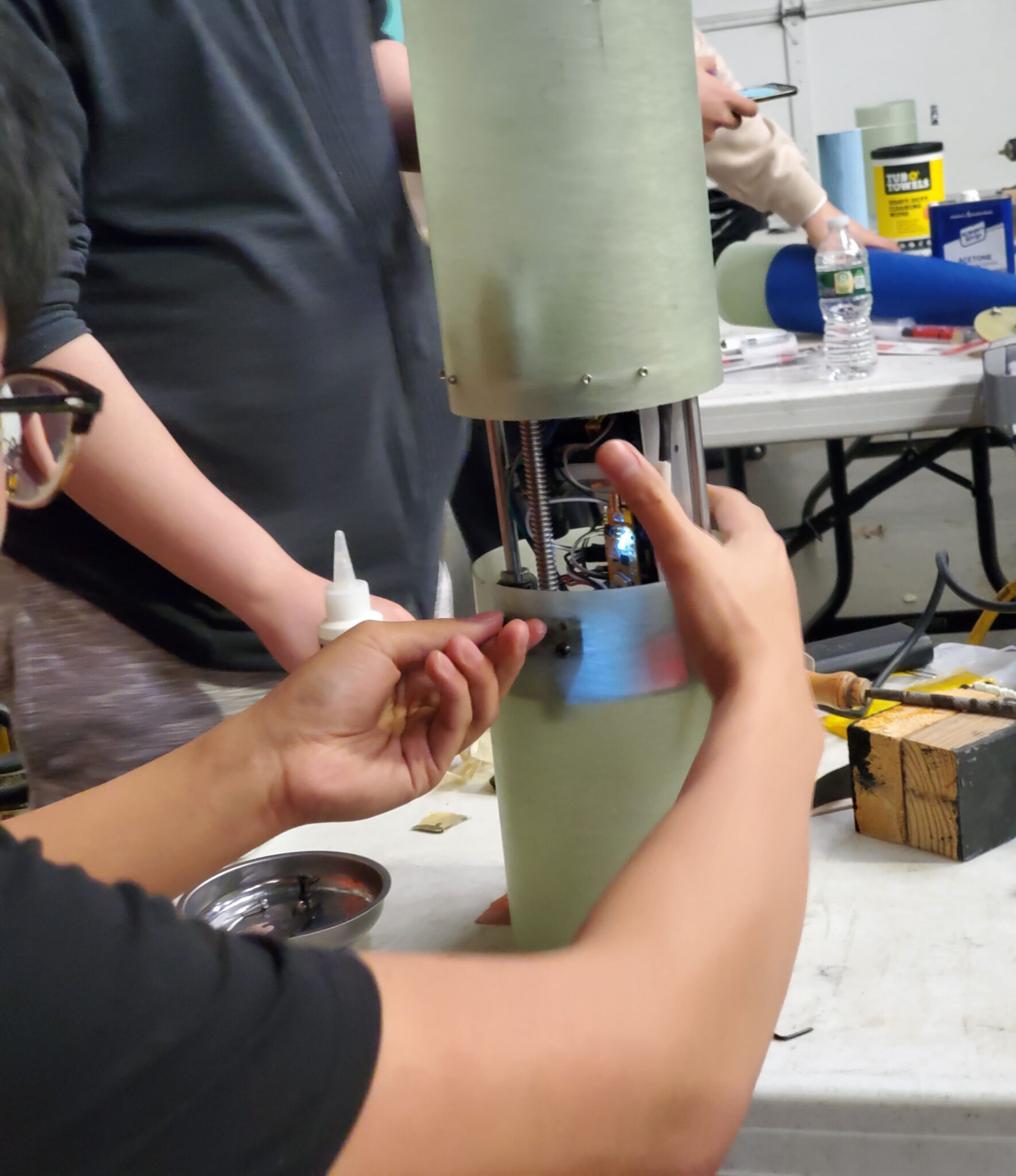
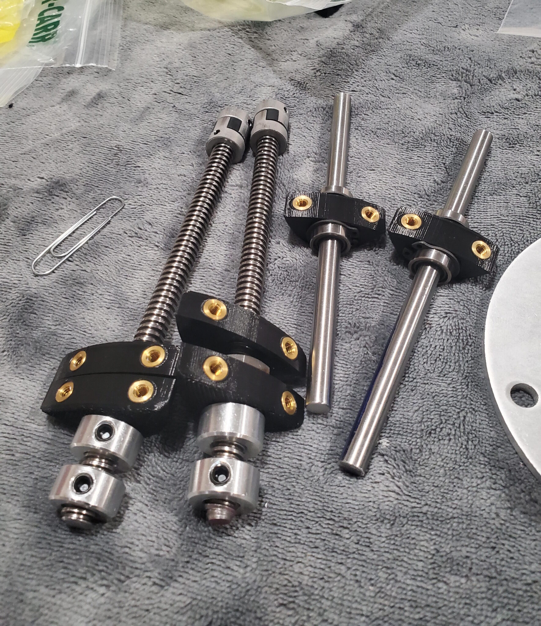
Payload Retention Mechanism: To protect the payload under launch and landing conditions, a horizontally separating mechanism reveals the camera system to the outside environment upon landing. Using a pair of lead screws, the casing can translate from a rigid closed state to fully deployed state via a captive nut with its rotation locked such that rotation of the screw results in linear motion of the nut and thus mount and casing. During testing it was found that the bevel gear coupling contained too much misalignment for reliable deployment, to solve this the lead screw was modified to become a rigid coupler to the DC gearmotor; this was possible due to the large difference in shaft size (4mm motor shaft vs 3/8in leadscrew) between the two parts, and allowed for the torque to be transmitted directly through the motor shaft to the lead screw reducing potential failure points in the design. One issue we ran up against was the two lead screws becoming misaligned and jamming under operation, it was found that one motor was damaged resulting in slightly lower relative speed, and replacing the motor alleviated the misalignment issues between the screws. A more ideal solution to this problem would be to implement a stepper style motor to have more repeatable operation, however was not able to be integrated into the design due to size constraints.
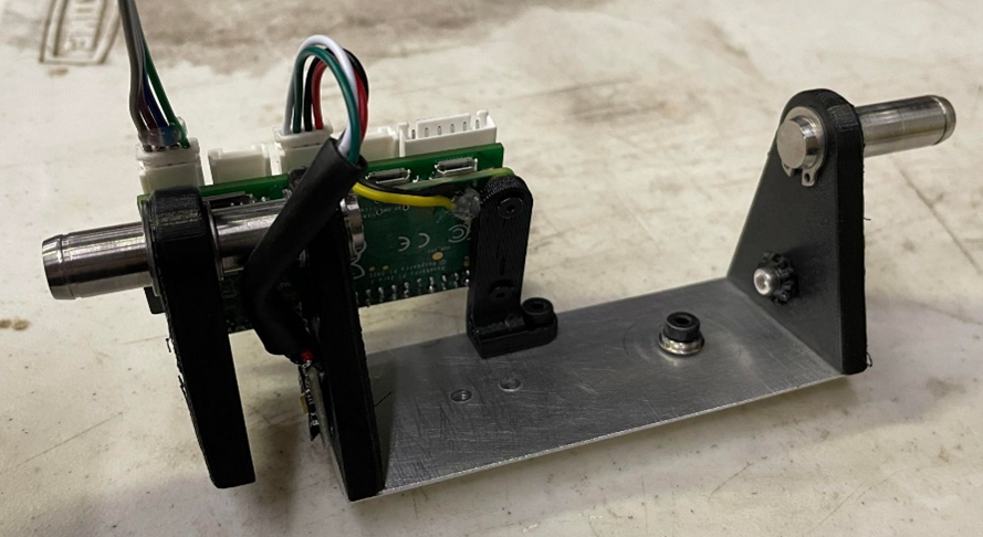
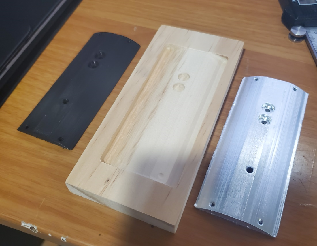
Camera Leveling Mechanism: The self-leveling mechanism is a passive assembly that ensures the camera and rack-pinion assemblies are level to the ground before deployment. This ensures that the camera can lift straight upwards above the bulkheads and take photos from the highest vantage point. The ends of the shafts are mounted upon bearings and can freely rotate upon the shafts and level itself using gravitational forces, this makes the system passive as no input power or processing is required to keep the table level. To allow the system to level passively the center of mass must be lower than the height of the center line through the bearings. During early design the CAD model constructed in SOLIDWORKS indicated a favorable center of mass, and additionally a prototype of the self-leveling table was tested, which demonstrated that the passive system works as expected and that the center of mass is low enough that it would level. To accomplish this the vertical holding arms and components on the table were 3D printed with the table itself being machined out of aluminum to further lower the center of gravity. On this table was all of the electronics required to operate the payload with exception of the lead screw motors and lithium-ion batteries, both being contained behind the aft bulkhead.
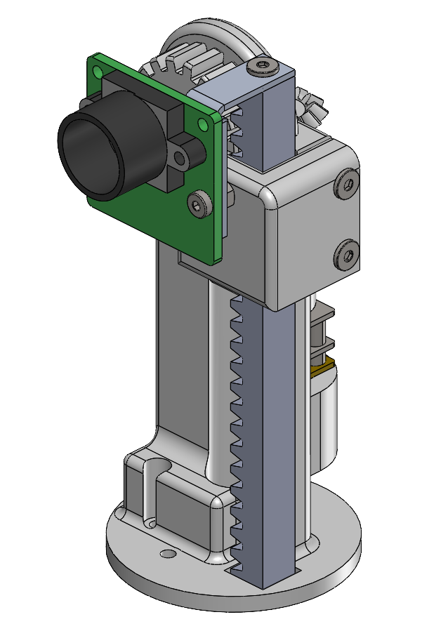
Camera Lift Mechanism: The camera lift mechanism provides the ability to extend the camera above the payload casing to allow for an unobstructed view of the surroundings with the selected camera module’s field of view in mind. The subassembly consists of a vertical rack that is raised by an elevated pinion. The pinion is driven by a bevel gear pairing powered by a DC motor. The entire subassembly is mounted to the camera rotation mechanism to allow for control of both the camera’s angle and height in a compact package. This mechanism contained the most complex geometry of the design, and as a result the parts were chosen to be 3D printed out of PETG similar to other parts in the design. While designing the mechanism, we had to pay special attention to the weight and height of the subassembly, as this naturally had a high center of gravity. Additionally the team had to perform FEA analysis of these parts to ensure that despite the low weight and high center of mass, the parts were capable of surviving launch and landing, with this attention had to be given towards ensuring the design was not only practical to 3D print, but also practical to assemble with hand tools and in short time.
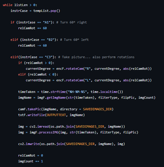
Camera Rotation: As part of the design, the camera system contained in the payload must be able to rotate 360 degrees to achieve a full view around the vehicle. To accomplish this the camera system was mounted to a large bevel gear with a flat face to mount the rack and pinion. Pairing this with a DC gear motor with magnetic encoder back to the Raspberry Pi, the camera can be autonomously rotated to any input angle. With the magnetic encoder a pulsed signal is sent back to the Pi six times per revolution, by counting the pulses counted an angle change can be calculated. The gear ratio of the paired DC gear motor was 298:1 with a gear set of 86:20, resulting in a maximum precision of +/-0.47 degrees. Additionally to protect against the rack and pinion wiring from being wrapped around the RP bracket the rotation of the camera would be limited to 240 degrees in one direction before switching directions and indexing -300 degrees to unwrap the wiring while still achieving the 360 degrees in 60 degree increments as required. Without the wiring attached the team performed tests of repeating the 60 degree movements 6, 12, and 18 times to check the accuracy of rotation, achieving our goal of +/-1 degree on all rotations.
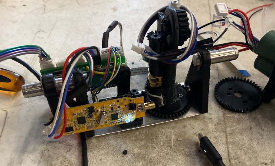
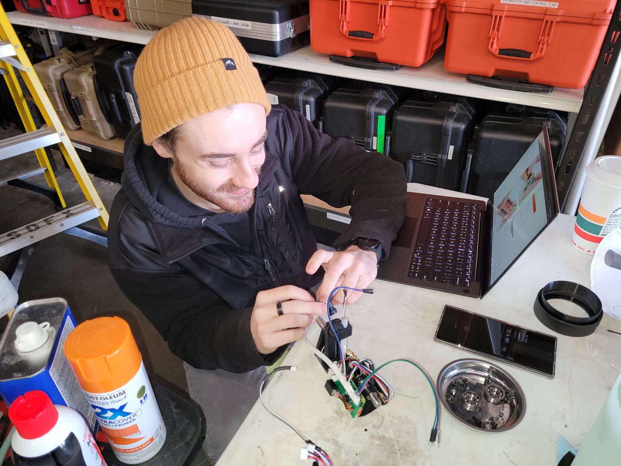
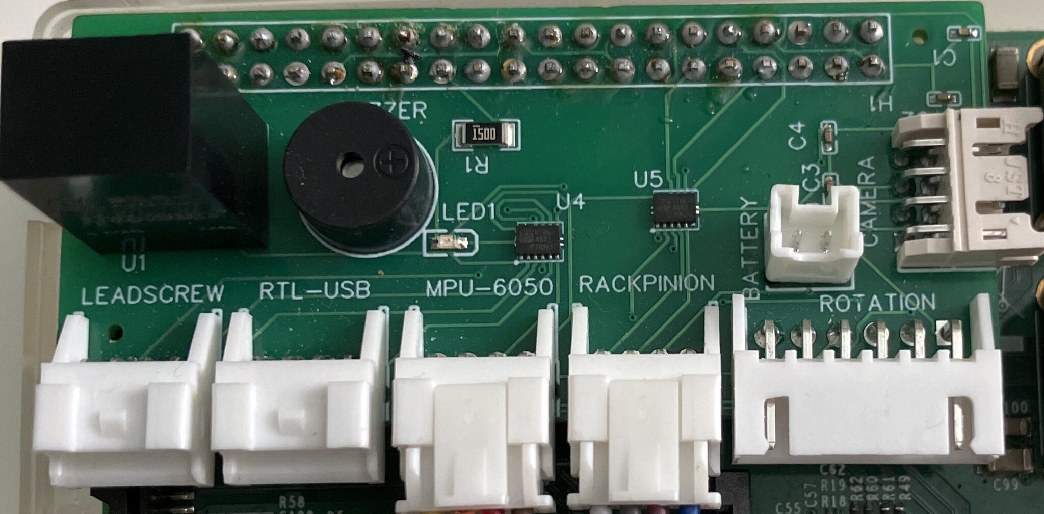
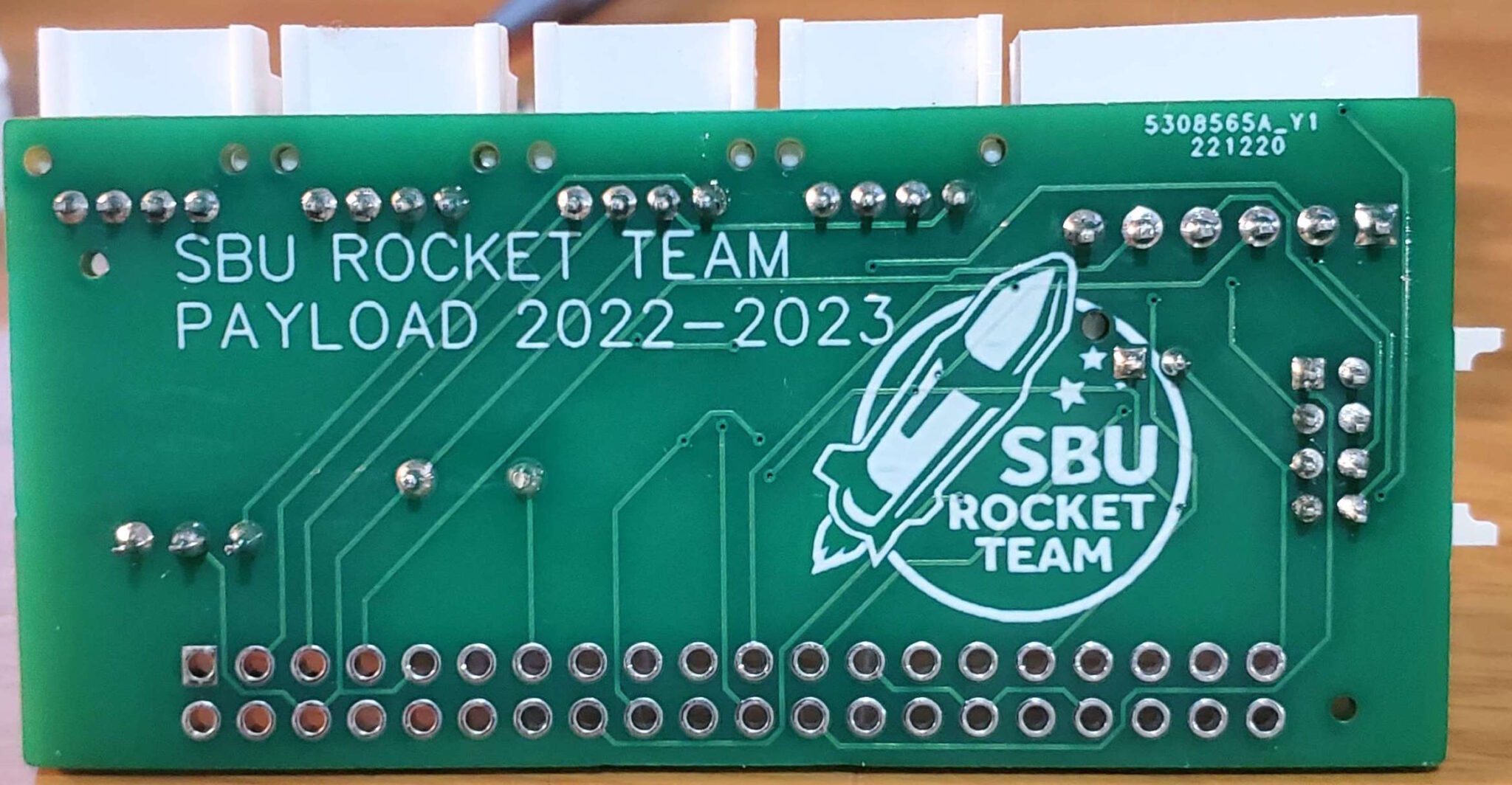
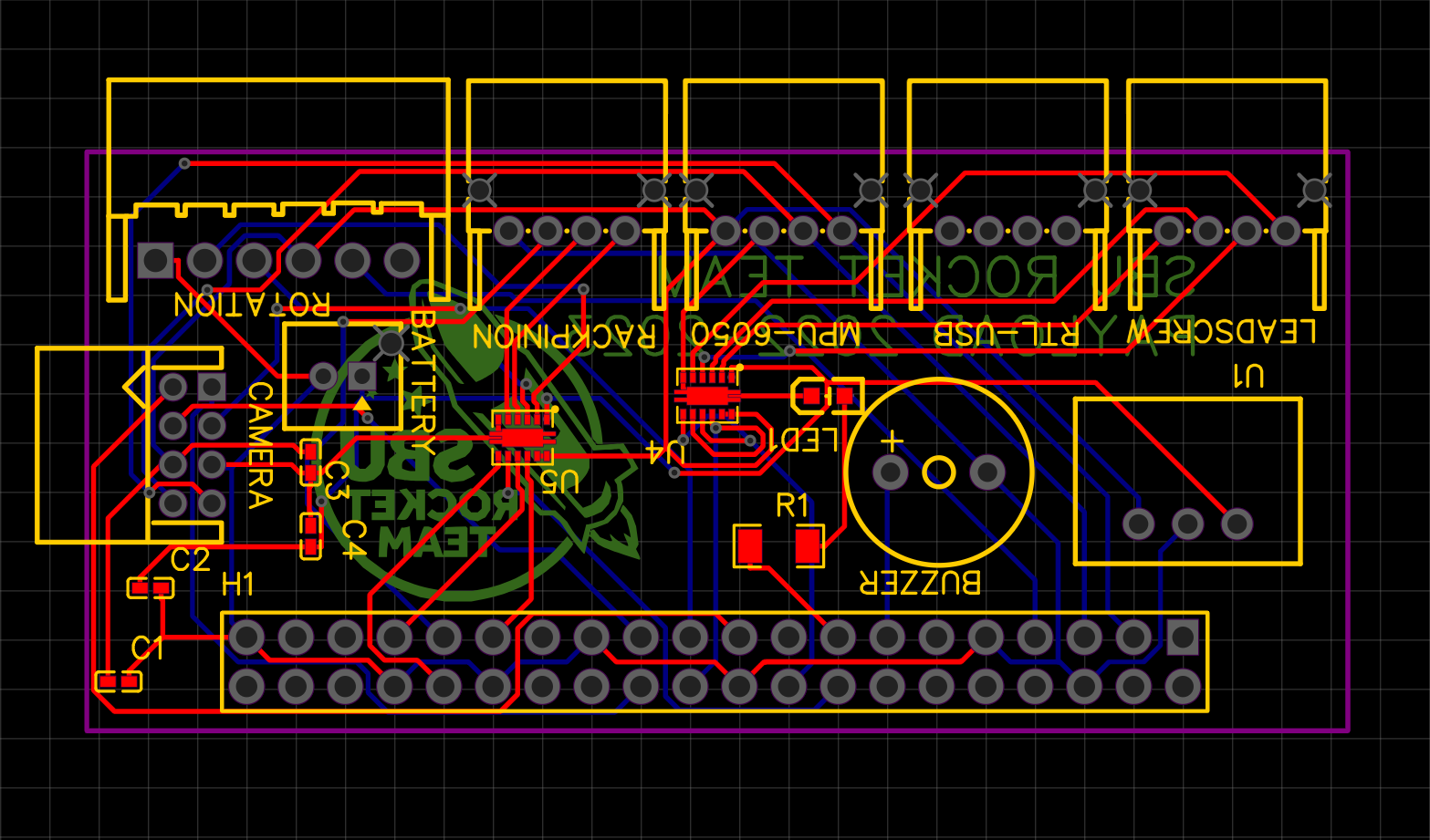
Onboard Processing and Custom Electronics: For performing the onboard tasks of the payload system contained, the Raspberry Pi Zero 2 W was chosen as the SBC. With a compact form factor, it is equipped with a 1 GHz quad-core Arm Cortex-A53 CPU with 512 MB of SDRAM. At such a small size it contains a relatively high processing power to allow for fast program executions as well as some simple image processing. It is also well equipped with 40 HAT (Hardware Attached on Top) header pins, microSD card slot, micro-USB useful for the payload’s requirements. Compared to similar sized small processing boards, the full featured SOC on the Zero 2 W allows to incorporate key features such as USB functionality into the design for use with the radio receiver without expending available GPIO pins. A custom PCB was favored over standard wiring to limit the number of free/loose wires within the payload. On the PCB, it contains all the necessary electrical components, DC-DC converters (Recom R-78B5.0-2.0), motor drivers (DRV8835), and trace connections to the point where the hardware just needs to be attached via the correct connector lead. An onboard LED and buzzer are also added as a tool for testing and debugging while writing the software program. The remaining hardware that will be connected to the Pi (through the custom PCB) will be attached through ribbon cable and JST connectors. This includes the camera, lead screw motors, camera lift and rotation motors, antenna, IMU, and battery. The battery that was chosen is the OooSure 2000mAh 11.1V 3S rechargeable batteries. It was ultimately chosen as the power source because it had the desired voltage, capacity, packaging, and size. For the connection to the rest of the electronics the batteries will be wired in parallel, since two of the same batteries are being used, the capacity essentially is doubled. During testing the battery capacity at idle was measured to be approximately 16 hours with one cell, and estimated at 2.10 hours at full rated power draw of every component.
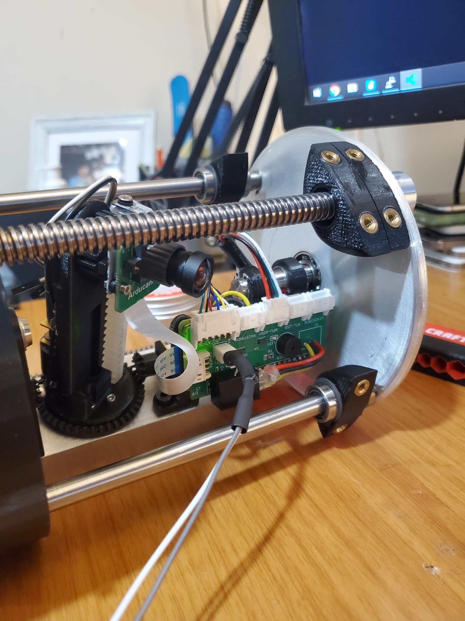
Camera Module: Originally, an Arducam OV5642 5MP Camera was selected as the main camera but was replaced by the Arducam IMX477 12MP Camera. This upgrade was due to the fact that the Pi Zero 2W could not interface with the OV5642 camera with picamera/picamera2 libraries. The IMX477 sensor compared to the OV5642 is a much more powerful sensor and the physical shield also has a smaller physical footprint. The IMX477 sensor is capable of an image resolution 4056 by 3040 pixels. We would not be using the full resolution of the camera as it would use a lot more memory and processing power for much lower perceptible visual returns. As a result, it would be limited down to 1080p or if applicable, 1440p. The camera shield is connected to the Pi through the built in camera ribbon connector. On the Pi Zero models, the port has 22-pins (compared to the standard 15-pins) while the camera has only 15 pins so a 15 to 22 pins ribbon is used to establish a connection between the two. The camera is capable of MIPI CSI 2-lane or 4-lane data transfer but the model B0262 only has 2-lanes which is fine since the Pi Zero 2 W also has a CSI 2-lane port thus won’t be losing any sort of additional performance. Per lane, it is capable of 2.1 Gbps data transfer rate, much more than what is required for the camera operations.
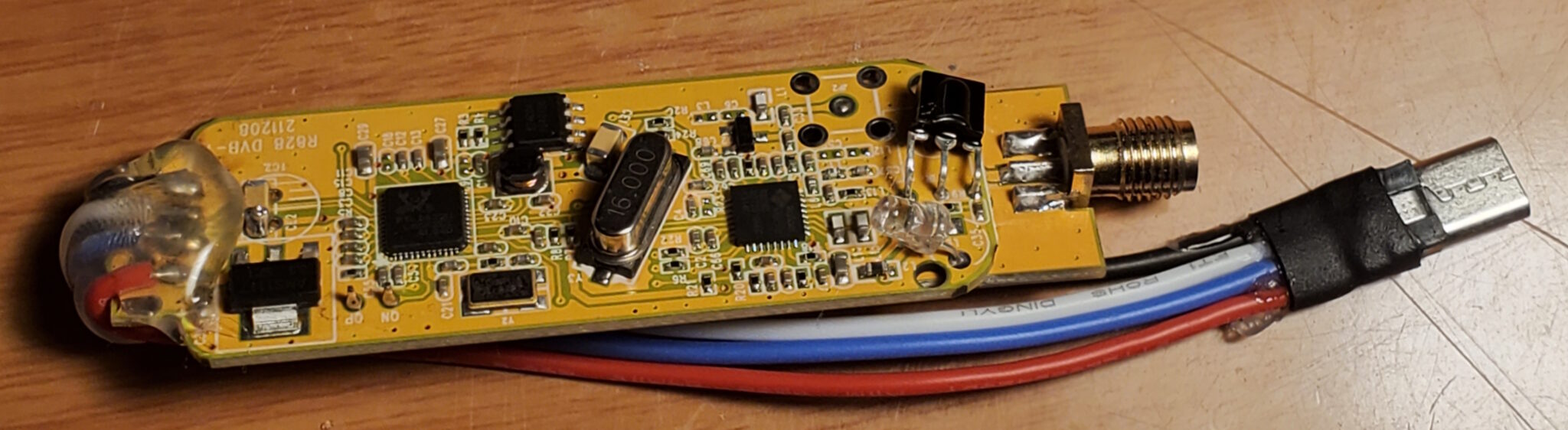
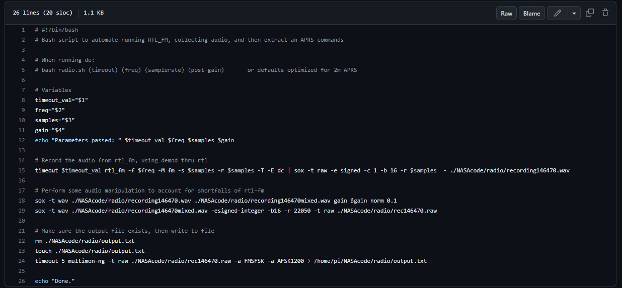
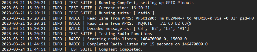
Radio Receiving and Decoding: For receiving of the radio communications on launch day, the payload assembly includes a software defined radio (SDR) to be able to programmatically tune into a required frequency and handle recording, tuner gain, and allow the onboard processor to decode the AFSK 1200 signal for the RAFCO message. The chosen component is an RTL-SDR V3.0 that connects and communicates back to the Pi through a USB-OTG connection. With fair Linux documentation and built in hardware automatic gain control (AGC) the RTL is observed to be operating at a sample rate of 1.08 MS/sec (mega-samples per second) when testing with ability to specify the specific listening bandwidth and resampling rate. For enabling use of the RTL-SDR in the payload design, some physical modifications were made to the original product in the form of removing the PCB from the metal enclosure, and resoldering the full sized USB type-A connector in favor of a micro USB connector for direction connection to the Raspberry Pi’s USB-OTG port. After a setup of the required drivers and packages the RTL was ready for use in Linux, then by using the bundled libraries of rtl_fm and rtl_sdr the device was confirmed to functioning by tuning to a local radio station and analyzing the recorded audio signals. By utilizing the various command line flag options of rtl_fm, the receiver can be adjusted in regards to the FM demodulation and tuner settings such as squelch level, tuner bandwidth, resampling rate, and AGC. For testing of radio reception, the following command was used:sudo rtl_fm -f 106.1M -M fm -s 1080000 -r 96000 -T -E deemp | sox -t raw -e signed -c 1 -b 16 -r 96000 - recording.wav
With the usage of rtl_fm, the audio output can be directly routed to another application. With this functionality the audio was recorded using sox, played directly through the audio output using aplay and decoding the AFSK1200 using multimon-ng.
Programming and Autonomous Control: For enabling autonomous control of the payload, the majority of the code was written in Python for use with existing libraries and tools, and then having the code run at boot/power-on. During development additional test programs were created to perform unit tests of certain components and subassemblies. The basis of the deployment code consisted of a general delay from boot to allow all transient movements to settle, then using the accelerometer to detect a high acceleration event by collecting, averaging, and then calculating the standard deviation of acceleration values. When a deviation in acceleration was found to be above the threshold value, the payload was known to be in a launch condition and move to the next portion of the code. Descent from apogee to ground level is limited to 90 seconds, so a delay of 120 seconds is used to prevent the payload from deploying prematurely, and then by looking for low deviation in acceleration, the payload is determined to be at rest. At this point the payload retention mechanism actuates, exposing the camera system and radio receiver, and enables to receiver decoding messages. With messages being sent every 2 minutes, the payload is set to listen for 6 minutes allowing at minimum two sets of instructions to be received and parsed, allowing for error checking between the two messages. From validating the instructions are within the listed sequence of possible commands, the payload then executes the commands using the camera system and saves the data onto the microSD card for retrieval and submission for grading. This deployment process allows the payload to function autonomously from flight to landing without any team intervention after the power switch is enabled.
Testing and Requirement Validation
RAFCO Requirement Verification
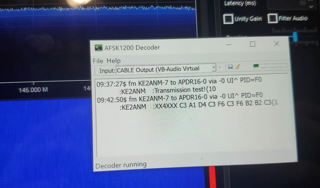
Testing of the payloads ability to receive and decode the RAFCO was done by emitting a test sequence over radio to ensure functionality at distance. To accomplish this, I had received my Technician Class radio certification (KE2ANM) to broadcast the RAFCO from any location. From this I was able to operate as an amateur radio station on the same frequencies to be used on launch day. The practice RAFCO was sent out using APRSdroid attached to a Baofeng UV-5R radio, sending messages to the appropriate callsign (KQ4CTL) as would be used on launch day. This was tested first at low power and close range outside normal hours as to not overuse the radio spectrum for sending repetitive digital messages. From confirmation the software was functioning properly the team conducted range tests to confirm the payload was sensitive enough to receive a RAFCO from the expected power antenna within our expected landing radius.
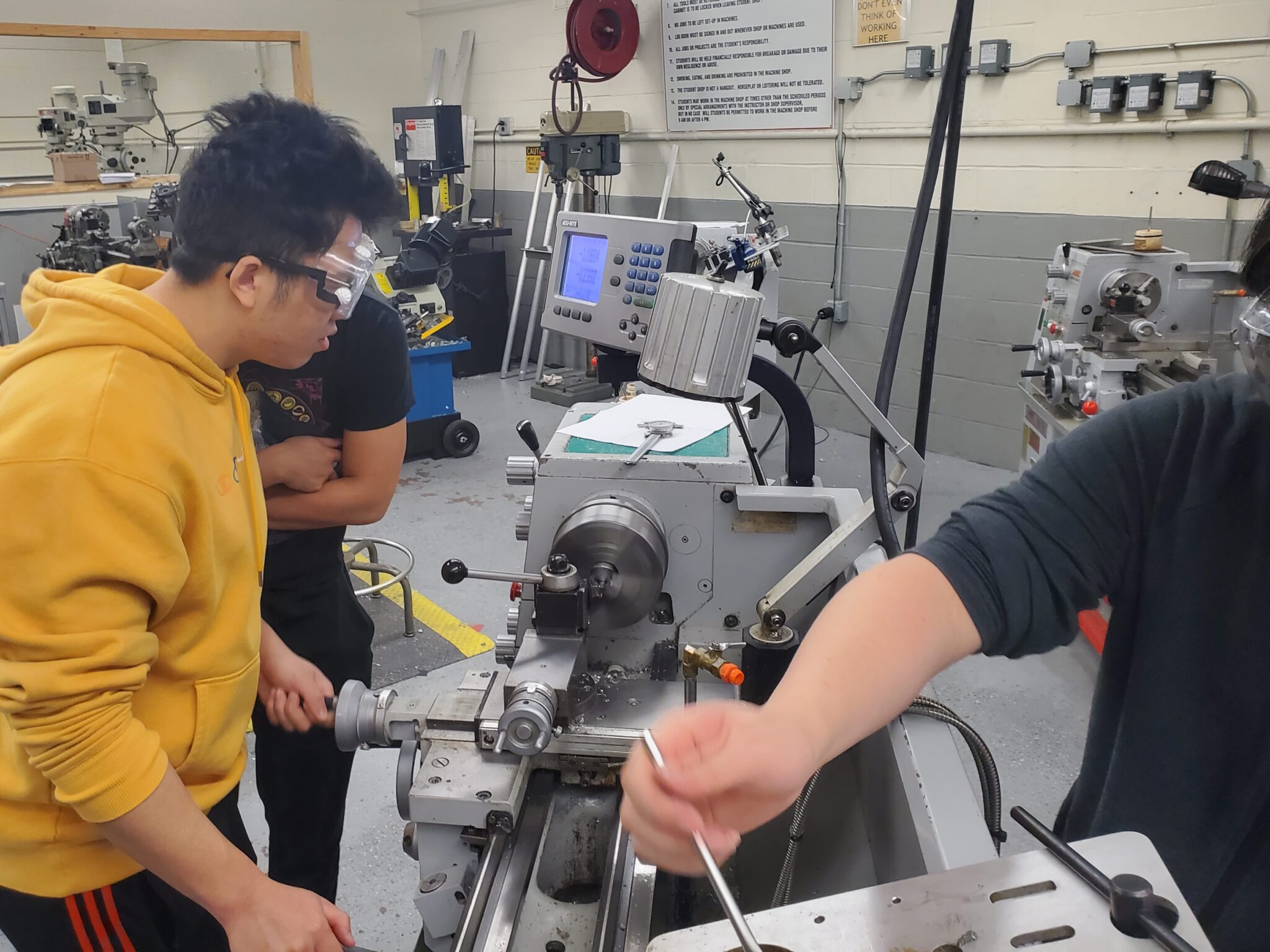
Mechanical Testing
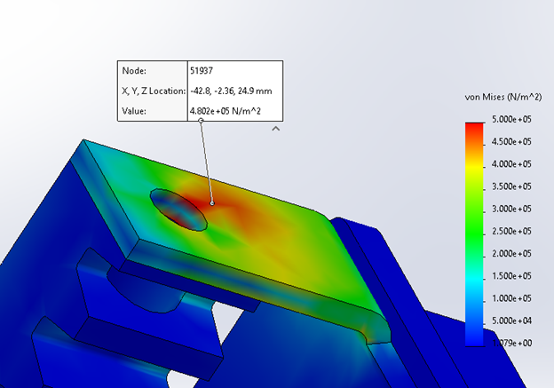
In addition to testing of the programming and payload functions, it is necessary that the payload is tested to verify it can survive launch and landing. In order to not have a situation where major design changes were required last minute, simulations were completed before construction of the payload or prototypes. For this we had to familiarize ourselves with SOLIDWORKS Simulation, running Finite Element Analyses (FEA) on parts of concern such as the rack pinion system, and the payload chassis. From the results of these simulations parts were then modified to pass our stress tolerances with an applicable safety margin. During construction we had also completed durability testing of the payload in the form of progressive drop tests until exceeding the kinetic energy predictions of the recovery simulations.
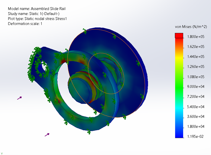
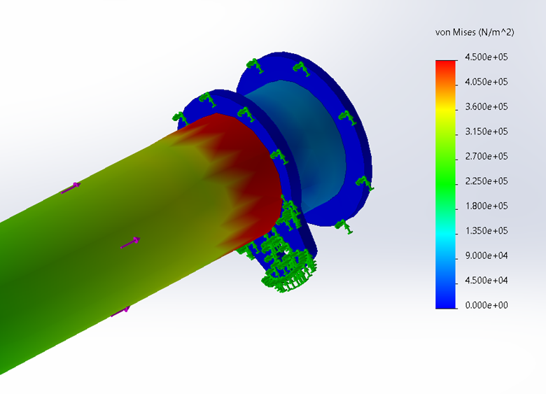
Some issues that we had found during testing and manufacturing was the lower than expected strength of the 3D printed parts. While we had an understanding that the simulation data was not entirely accurate due to the process of 3D printing both deteriorates the material properties as well as yields differently depending on the print orientation and slicing layer plane, some weaknesses were only detected during testing. Notably the 3D printed holding arms that secured the aluminum swinging table to the bearings in each bulkhead had too small of an offset from the dowel bore, resulting in fracture and separation during testing. By changing the print orientation and settings, additional strength was added back, however a redesign of the part to introduce more material was necessary to achieve the factor of safety desired. Similarly the original design of rack and pinion holding bracket was very slim to keep the center of mass low, however when analyzing each layer’s cross section there were locations of high stress concentration confirming weak spots in the design, which we had also confirmed with mechanical testing of these early parts. To remedy this additional material was added to dissipate stress, and larger fillets were added to the edges to reduce stress concentrations around changing geometry.
NASA USLI Reporting and Conferences
As part of the challenge, the team is required to submit reports to NASA documenting our design concepts, construction progress, and flight results. This includes a Preliminary Design Review (PDR), Critical Design Review (CDR), and Flight Readiness Review (FRR). With each of these reports, each component of the vehicle is described in detail as well as findings from simulation results, unit testing, and construction drawings and documentation. Notably the PDR describes the payload design concept of how to meet each requirement listed in the handbook, with preliminary prototyping and testing. The CDR is a more thorough analysis of the payload design including simulations and unit tests. It is here that the manufacturing documents and plans are made and some more advance prototypes take shape. For the FRR the design is to be fully constructed, tested, and then demonstrated on a full scale launch and landing of the vehicle and payload ahead of a final launch in Alabama. To accompany each of these reports, a teleconference is held between the team leaders and the NASA staff running the USLI event. Here the team presents the work and findings of team to a panel of engineers and subject matter experts, and then answers questions about the design feasibility, safety, and any other concerns in regards to the vehicle or payload.
Conclusion and Reflection
Reflection on Personal Growth and Skill Set Development
Throughout my journey as the Payload Team Leader for the NASA Student Launch Initiative, I have experienced significant personal growth and skill set development that will undoubtedly contribute to my future success as an aspiring engineering professional. Taking on the responsibilities of overseeing the project’s direction, managing a small and diverse team, and working closely with NASA representatives provided me with invaluable insights into real-world aerospace projects and their challenges. My involvement in various aspects of the project, from mechanical and electrical design to programming and fabrication, allowed me to expand my technical expertise while pushing past my comfort zone. By taking the initiative to self-learn and collaborate with teammates from different backgrounds, I enhanced my problem-solving, adaptability, and communication skills. Additionally, the project management aspect taught me the importance of balancing rigorous deadlines and maintaining a healthy team dynamic. Recognizing and addressing burnout, encouraging equal contribution, and celebrating team accomplishments fostered a positive and collaborative work environment. Overall, the experience gained through the NASA Student Launch Initiative has been transformative, equipping me with the necessary skills and confidence to tackle complex challenges and excel in the aerospace industry.
Reflecting on my personal growth and skill set development, working on the mechanical design aspects of the project, including the camera lift and rotation mechanisms, played a significant role in broadening my understanding of mechanical design principles and the challenges associated with creating efficient and functional systems. By developing and integrating intricate subassemblies, I gained hands-on experience in considering factors such as weight, center of gravity, and structural integrity, as well as optimizing designs for manufacturability and assembly. The use of parametric modeling in SOLIDWORKS allowed me to quickly adapt to design changes and make informed decisions based on the available resources, such as 3D printing with PETG and CNC milling with sheet steel and aluminum. Additionally, performing Finite Element Analysis (FEA) to ensure the robustness of the design during launch and landing further solidified my understanding of the importance of meticulous analysis in engineering projects. Through my involvement in various mechanical design tasks, I have honed my skills in material selection, optimization, and design for manufacturing, all of which contribute to a well-rounded skill set that will be invaluable in my future endeavors as an engineering professional.
Challenges Faced and Lessons Learned
Throughout the NASA Student Launch Initiative project, our team faced numerous challenges that ultimately led to valuable lessons learned and personal growth. As the Payload Team Leader, I was responsible for managing a small, high-performance team, which required striking a balance between individual strengths and fostering an environment that promoted shared learning and collaboration. One of the most significant challenges we faced was adhering to tight deadlines, which necessitated efficient time management, prioritization, and quick decision-making. The project’s dynamic nature also required us to be adaptable and learn new skills rapidly, often involving self-teaching and researching unfamiliar concepts. This experience reinforced the importance of continuous learning and resourcefulness in the ever-evolving aerospace industry. Late-stage design changes and rapid iterations between prototypes presented additional hurdles. By employing parametric modeling and rapid prototyping techniques, we were able to quickly adapt and optimize our designs to accommodate new requirements, minimize waste, and maintain project momentum. This iterative process taught us the importance of flexibility, resilience, and embracing change in engineering projects. In summary, the challenges faced during the NASA Student Launch Initiative project provided us with invaluable insights into the realities of working on complex aerospace projects. The lessons learned in areas such as teamwork, adaptability, time management, and embracing change have not only contributed to our personal and professional growth but have also prepared us for future success in the engineering industry.