Reverse engineered and designed custom parts to upgrade my 3020 desktop CNC to up to 100% higher feed rate and depth of cut with better surface finish. This was done using a 1.5kW spindle representing a 400% increase over stock spindle power, replaced all stock 8mm acme lead screws with 16mm ball screws reducing backlash by 90% to better handle the 170% increase in cutting force by upgrading from NEMA 17 to NEMA 23 stepper motors.
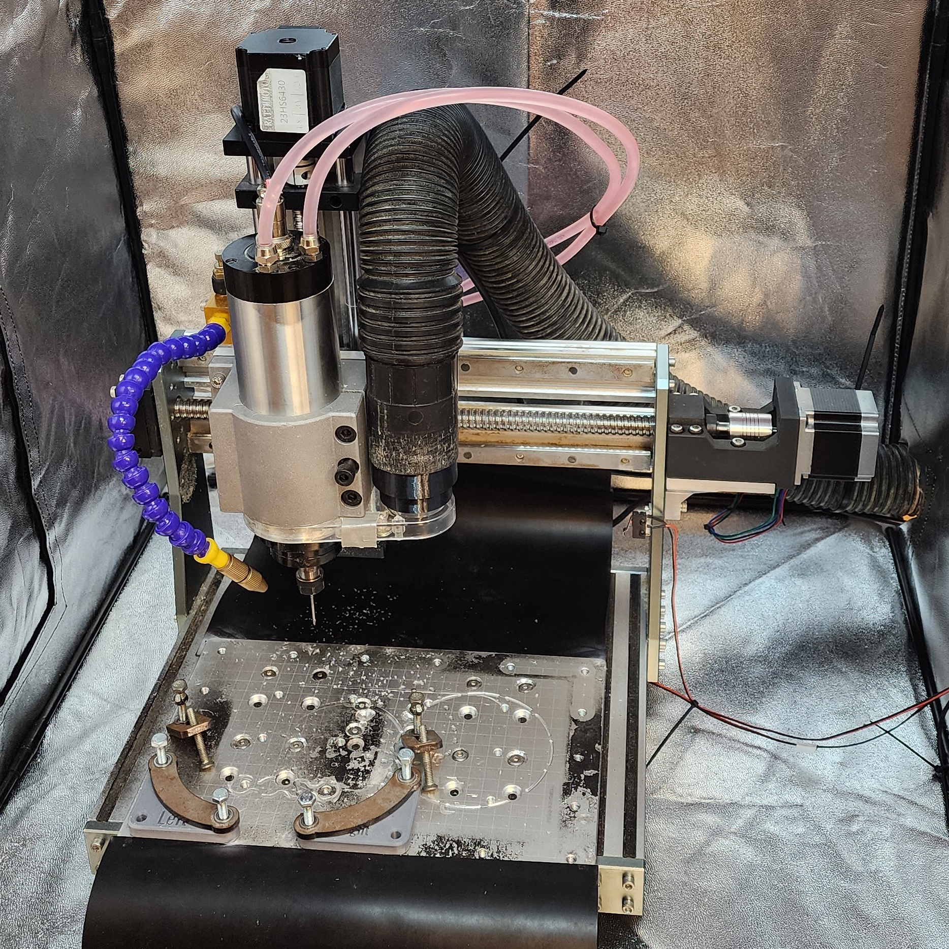
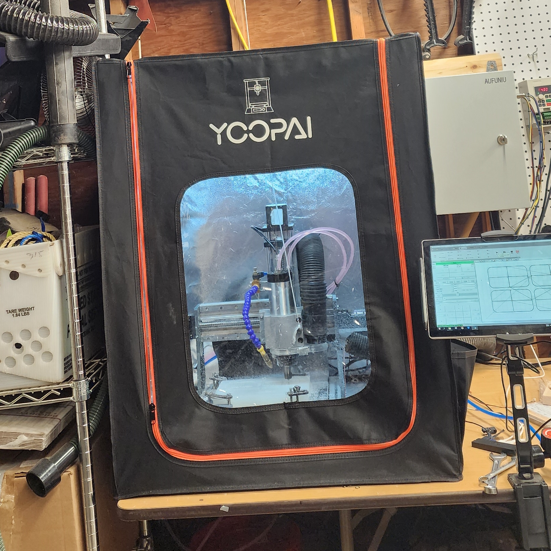
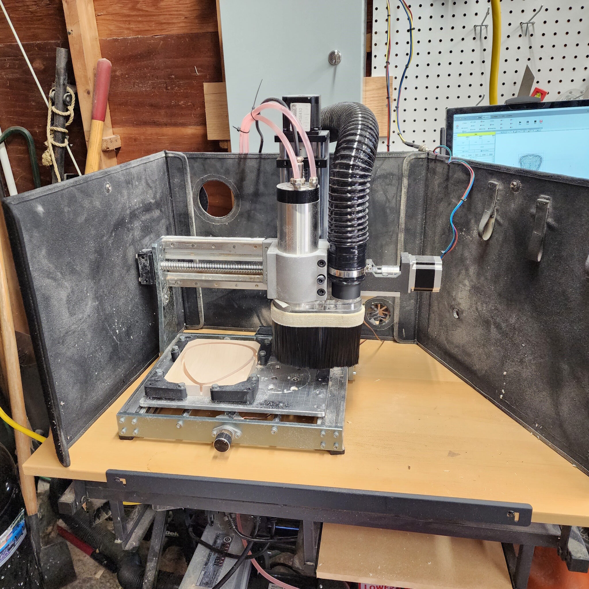
The before and after, from 300W machine to 1.5kW workhorse.
My problems, and my goal
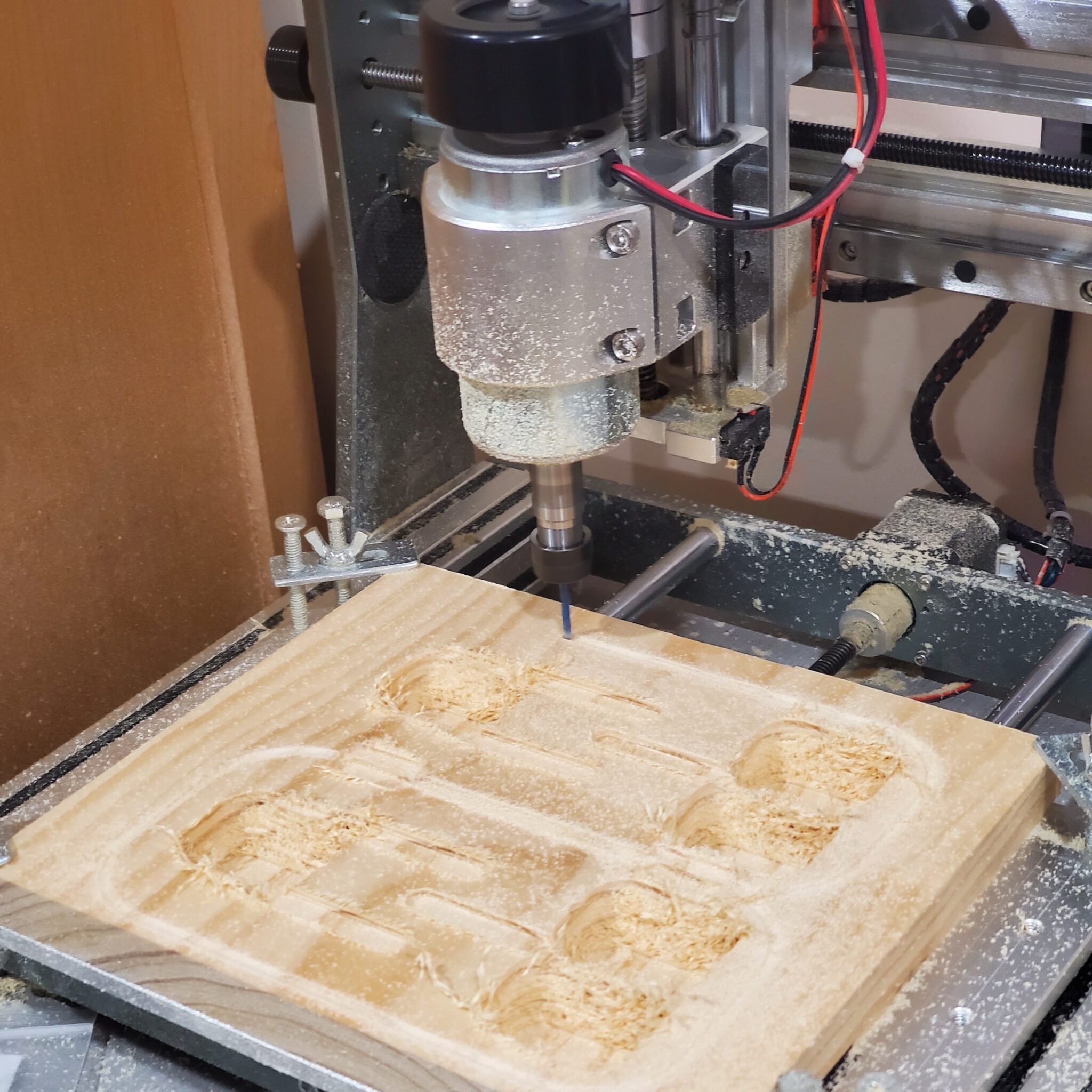
Around the end of 2022 I got into CNC milling with a Genmitsu 3020 desktop CNC mill, a common entry point into CNC for the home workshop. The machine had all the features I could ask for considering the price of the unit. However, as my knowledge and abilities in CNC grew I started wishing for some added power my machine just didn’t have from the factory. And what started as needing a new spindle for some more power turned into replacing lead screws reducing the amount of ‘looseness’ in the screw, upgrading to larger stepper motors allowing for greater cutting force, and switching to a water cooled VFD spindle for all day machining capacity. But as you’ll see, the upgrades were worth it and allow me to run more depth and feed rate than before, and do it all day staying cool.
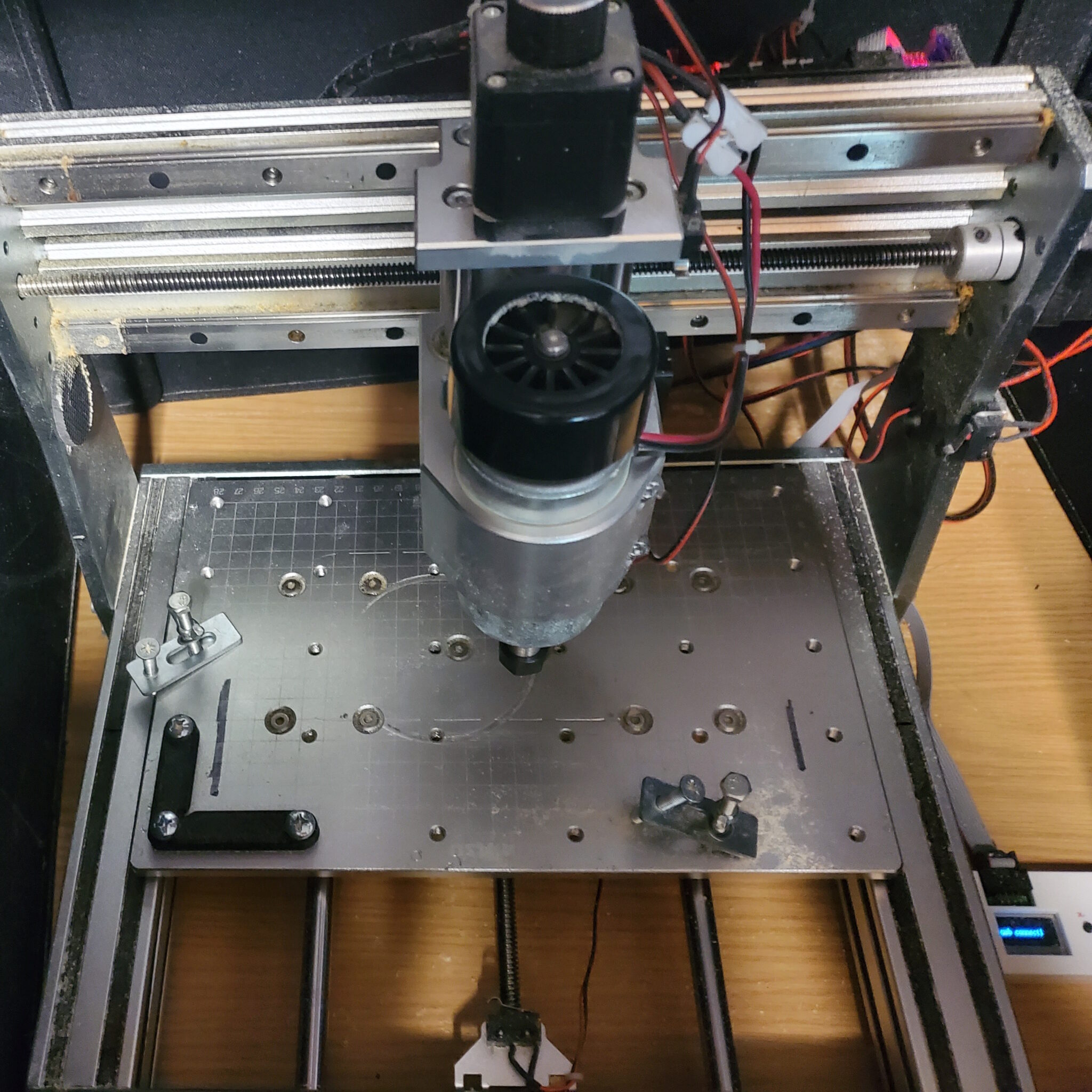
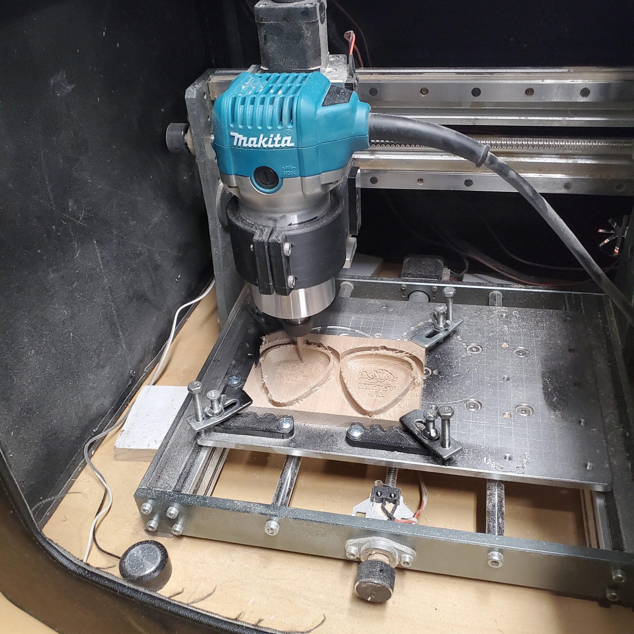
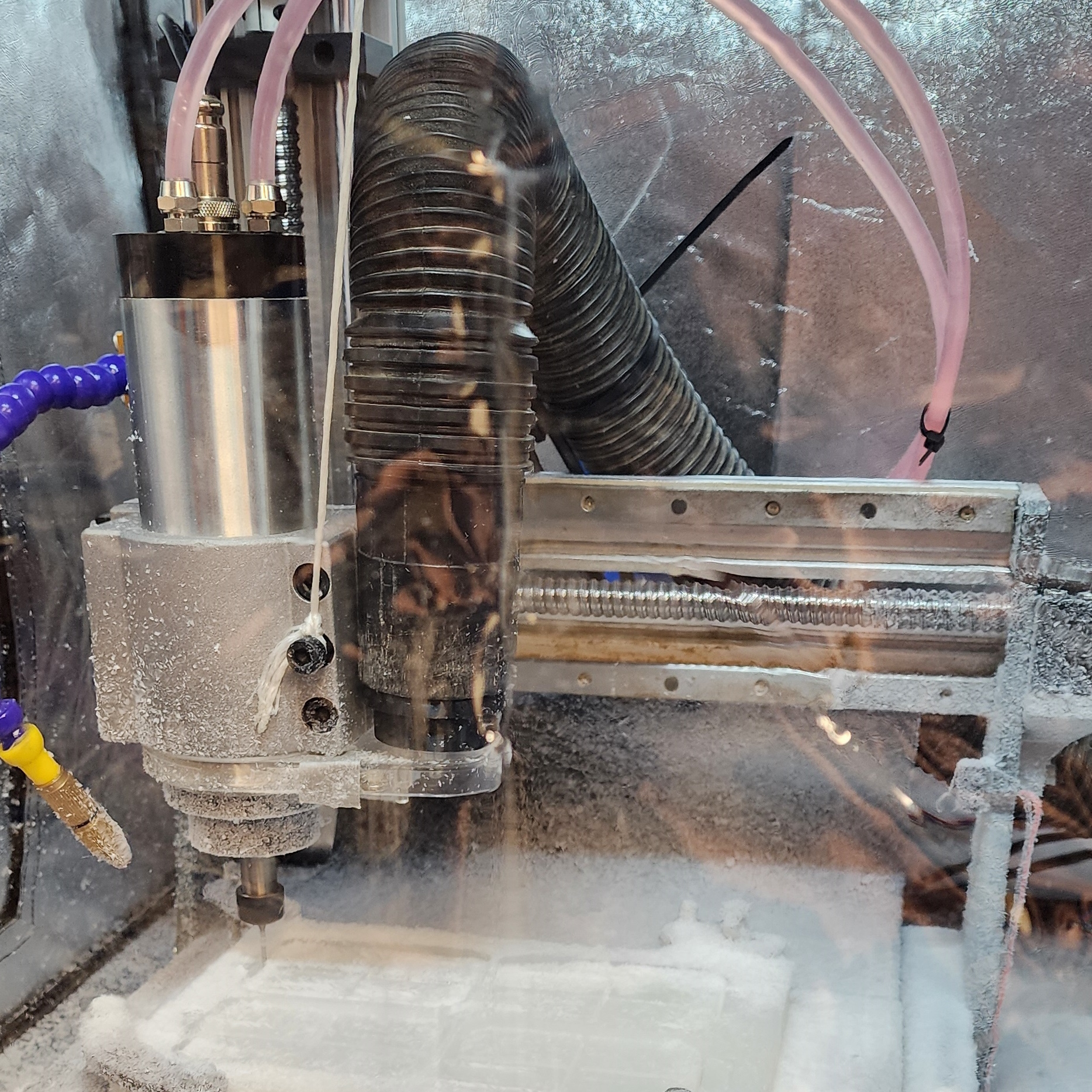
This all came about when my included spindle (300W) died from extended batch use, and I then switched to an 800W Makita RT0701C Router with a 3D printed mount. At the time I was making batches of some small woodworking projects and products and the router was a substantial upgrade over the stock 300w DC motor. This worked okay for a while other than the noise level, and ended up lasting about a year before giving up the ghost. I needed a new option that I could run for an extended period of time with high power and low noise so I opted for a liquid cooled 1.5kW VFD spindle allowing for long and tough operations at steady cool temperatures.
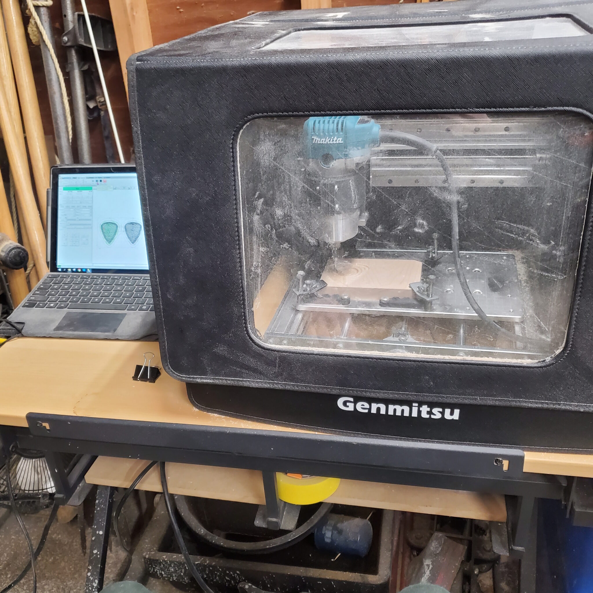
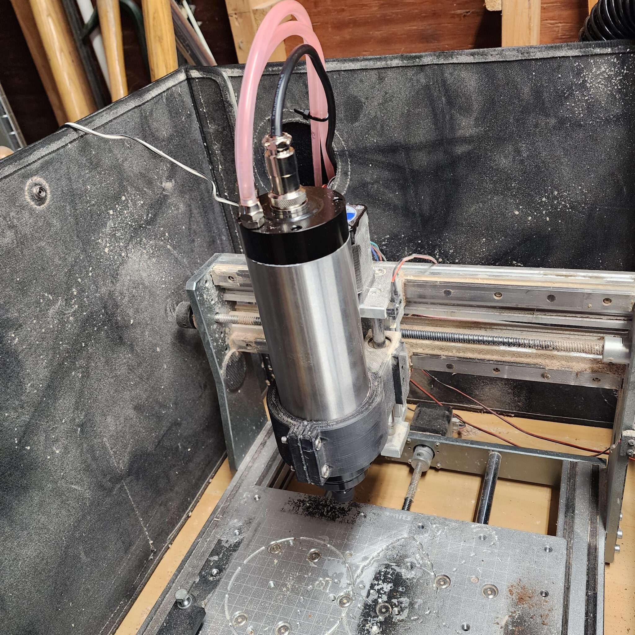
I learned quickly after test fitting the new spindle in the old 3D printed mount that my enclosure would no longer fit
The Technical Dive
As expected, none of the new parts I specified for the project were able to be drop in replacements for my machine so additional new parts would need to be designed and fabricated along with some drilling and cutting of the original chassis to mount everything together. I had figured that while I have the machine offline for the new spindle, I may as well upgrade the screws and steppers to handle the extra power and remove the backlashing ruining my machines accuracy and performance. Critical to making this work was finding someone had already constructed an accurate CAD model of my stock machine, which allowed me to download and import it for modification with my new parts list. Then as each new piece was added to the CAD design, new components were designed to fit the new parts onto the existing frame and parts to form a more performant CNC machine.
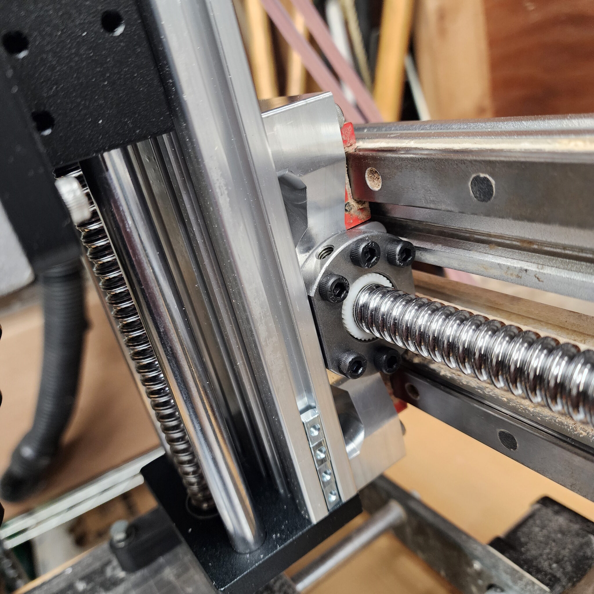
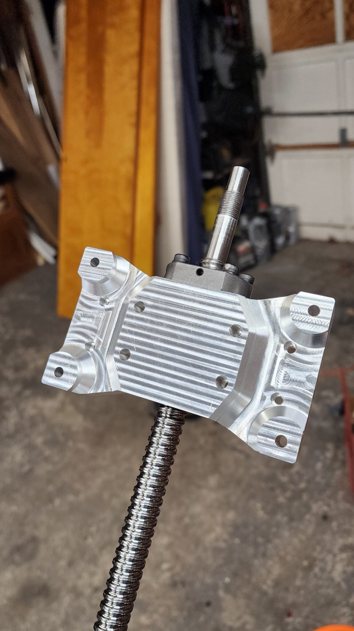
X-axis adapter carriage
This piece was the heart of the upgrade so the speak. This would tie in all the new upgrades for the X-axis with the new Z-axis to the existing bearings on the frame of the machine. This part was designed to be made of aluminum and featured geometry to remove excess material keeping weight and inertia down while maintaining strength. To manufacture this part a 5-axis CNC would be recommended so the design was contract manufactured by PCBway with their 5-axis capability. The featured geometry of the part include the through bore and mounting pattern for the ball screw nut, the patterns for mounting to the linear bearing blocks on the CNC’s frame, and the pattern for attaching and carrying the Z-axis assembly.
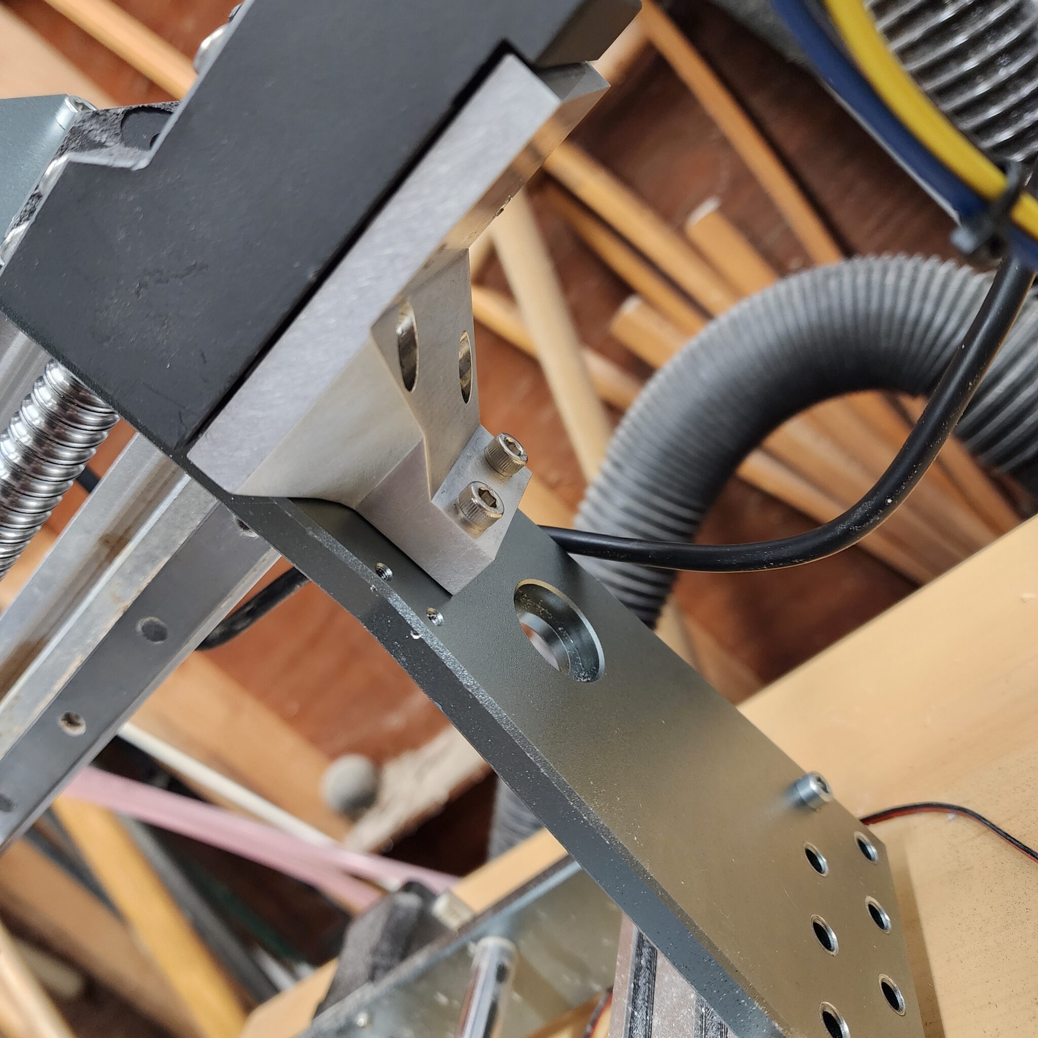
Stepper motor mount adapters
For attaching the new larger stepper motors to new ball screws on the X and Y axis of the machine, I opted to use the included motor mount but I needed a way to mount these two pieces which lay perpendicular to each other and must be strong enough to transmit the cutting forces from the motor to the spindle without deflection. For the X-axis I had decided to go with a CNC machined part adapting the stepper mount to a hole pattern I would drill and tap into the machine frame. This worked out well as the part was strong and rigid, but wildly expensive for its requirements.
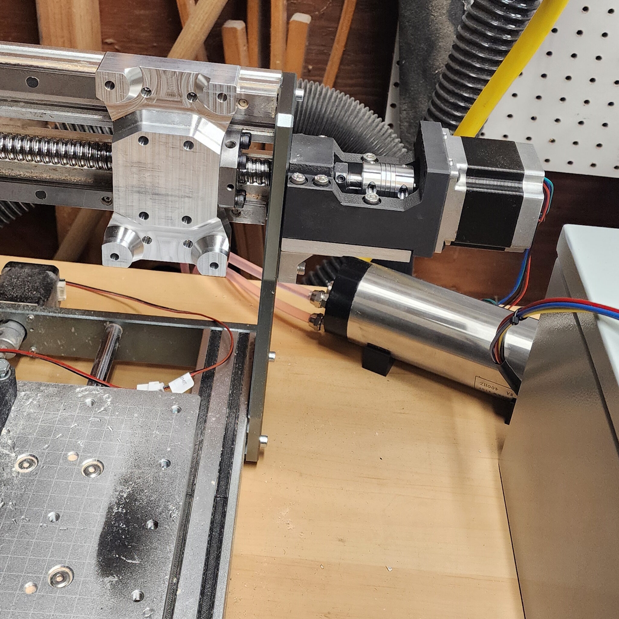
For the second go, now with the Y-axis, I decided to try using a bent aluminum flange piece with the required mounting holes and threads laser cut then tapped in where necessary. This had lowered the price of the part down 43% to $28.34 compared to the original CNC part with the same function. In the future if a similar upgrade is attempted again, I would choose to go for laser cut steel flanges rather than aluminum for added rigidity over the current aluminum version in use while not needing to change any geometry of the design.
Electronics Mounting Enclosure
An off-the-shelf electronics enclosure was purchased with had a removable panel that I then mounted all electronics to using custom 3D printed mounts and rivet-nuts in the panel. Originally the case was specified to be large enough to hold TB6600 motor controllers but was abandoned for the integrated A4988 motor drivers on the control board due to incompatibilities. This left extra room to add controls for potential future upgrades.
Outcome
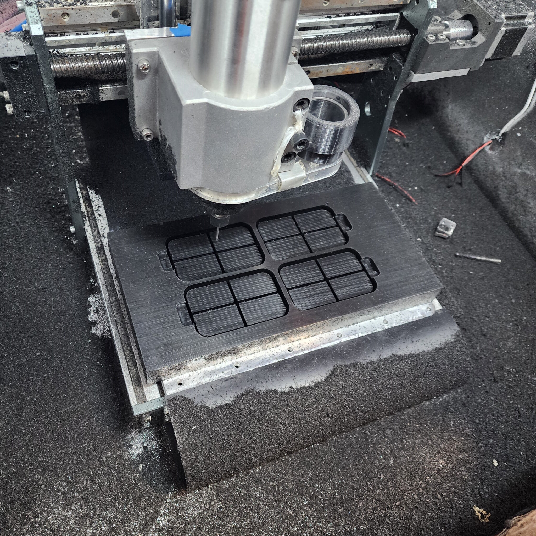
Mounting of the commissioned parts went without issue, with the only additional modifications needed to be made being shifting the work platform of the CNC forward to adjust for the further forward spindle, and align the spindle to be concentric and square with the work bed (known as tramming). As a beginner in CNC a lot was learned by tearing everything down to the individual nuts and bolts of the machine and seeing it all in CAD to understand how each of the parts connect and function. But the assembly gave me some challenges with trying to tram the spindle to the concentricity advertised by the spindle seller, teaching me a lot about how squareness and concentricity matters on the CNC and will translate into errors/artifacts in the workpiece. By making these upgrades I have already found the next bottleneck in making the machine run better. One piece of work that still needs to be incorporated with the current upgrades is connecting and configuration with the CNC controller for programmatic control of the spindle speed. Regardless, with the current upgrades I am able to run the machine with at least 100% higher feed rate or depth of cut and still have a higher quality surface finish than previously.
Takeaways
The most challenging part of the design was ensuring the added X-axis screw mounts were perfectly parallel with the existing X-axis linear bearings, as well as making sure the added mount points for the new Y-axis ball screw were aligned with the linear rods and bears of the Y-axis. Any misalignment from the screw to the existing bearing surfaces would lead to binding and extra friction on the screw potentially damaging the screw or steppers. The main skills demonstrated with this project was my CAD proficiency to reverse engineer a solution to my existing CNC setup using mostly off the shelf parts, and problem solving around issues such as incorrect schematics, and needing to make irreversible modifications to the CNC frame for mounting. This has also taught me how to think differently about backlash and squareness in regards to how that transfers to the workpiece accuracy and quality, most notably the improvement in max feed rate, vibrations, and stability in deep contour cuts which struggled on the old setup.